Passing the Torch

My Grandfather was an excellent carpenter. I inherited his Audels handbooks on how to create various wooden structures. It is fascinating reading how to build a barn without using nails. I doubt I will ever need to accomplish that task in my lifetime. My dad was an engineer before me. I also inherited

his engineering reference books and his slide rule. He did his best to pass the torch on to me, I do not foresee ever designing another oil refinery. Each generation has new challenges to undertake. Now that I have the torch, I must determine the best way to pass it on to the next generation. Fortunately I am not alone in wanting to transfer skill to the new generation.

Woody Flowers an MIT mechanical engineering professor also saw the need to pass the torch. He put together First Robotics as a tool for teaching high school students how to accomplish the engineering tasks associated with designing and building robots. His brilliance shows in that he made the journey fun for the participants, First Robotics has grown into a world wide competition that attracts aspiring engineers.

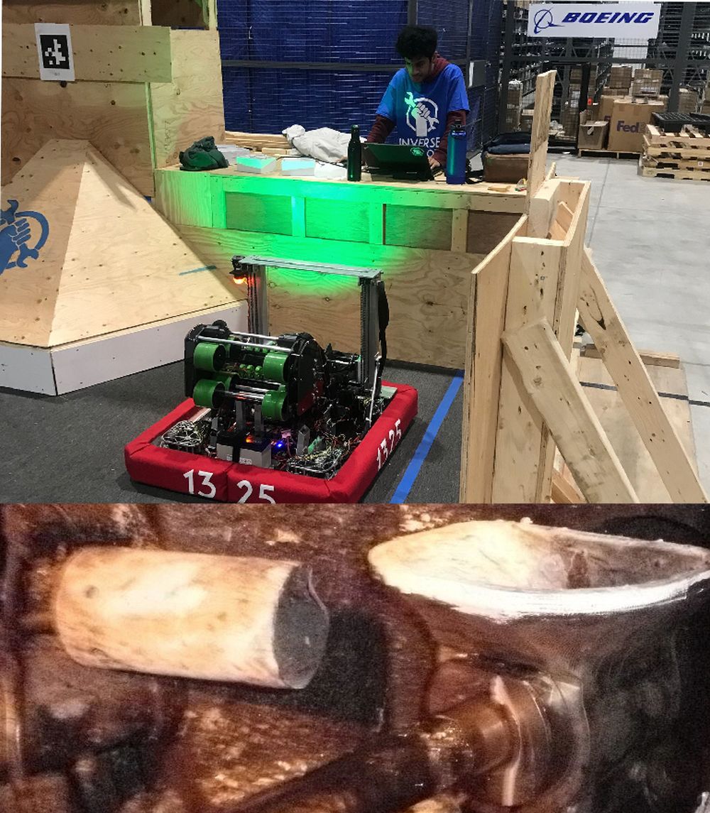
I volunteer mentoring a local team. Pictured is the robot that the students designed for this years competition. The alumni of our team have impressed a few of our industry sponsors who are equally concerned about passing the torch. The support of sponsors only improves the training we can impart

Die Casting has shrinking number of North American Companies that use the process. This is in spite of the rising amount of aluminum used in vehicle manufacturing. Some of my skills such as creating the 3D models for the new larger size torch heated funnels (launders) that are a part of the new Mega Casting cells are being taught to the students that invent the First Robotics competition robots. Otherwise the education system is reverting to saddling the graduating students with massive debt without the skills needed to repay it.

Spaghetti

Gigacasting die hoses look like spaghetti

I always find a good dish of spaghetti attractive. My wife buys our favourite tomatopasta sauce and adds in the meatballs. In all the years of eating spaghetti I have never counted the number of strands on my dish. Usually they are eaten before that is possible. I cannot imagine having to number each of the strands of spaghetti that are on my dinner plate. Numbering the hoses feeding a gigacasting die is just the beginning of utilizing them to achieve the correct temperature distribution in a die

Now we have gigacasting dies. As you can see in the picture more than 100 hoses are connected to each half of the die. The “spaghetti” gets worse when you realize that each hose feeding the die is looped into 3 to 7 thermal passages within the die. I am not surprised. Elon said that a gigacasting combined 70 pieces into one. The thermal passages you would use to make 70 individual casting dies got incorporated into a single die. Even the huge slides used to create the rear wheel housings have a large numbers of percolator style thermal passages in the fingers that form the rear rail section.

Die casting dies that are at room temperature do not produce good castings. Die preheating is used to avoid scrapping up to 100 castings to bring the die up to steady state operating temperature. Gigacasting dies weigh 100,000 Kg. Using the 490 J/Kg C heat capacity of steel, 160 Kw Hr of power input is needed to increase the die insert temperature to 100C and raise the holder temperature to 75C assuming no losses. Actual heat input requirements are double that factoring in convection losses and platen heating.

A pair of 90 KW hot oil Thermal Control Units (TCU) happily preheat a gigacasting die for prototyping if left on overnight. When a long preheat period is available other issues like having enough heat transfer passage length are not a concern. Gigacasting integrated into an assembly plant is another issue. 2 hours of assembly plant shutdown waiting for a die to preheat is an eternity, I suspect that the hose “spaghetti” we see is to enable the use of 5 additional 48KW TCU’s to reduce the preheat time to under an hour.

Biscuit

Gigacastings also need biscuit thickness control

It is easy to think about biscuits at this time of year. My wife and I bake a whole bunch of them to pass around at this time of year. As this Gigacasting image shows the casting operator was also thinking about other types of biscuits.
Control of biscuit thickness is normally a significant process control variable. Even if the molten metal delivery device is able to accomplish perfect weight dosing, other causes of biscuit length variation must be controlled. Die blow and flashing also vary casting weight which show as a biscuit thickness variation Usually a minimum biscuit thickness is needed to insure that molten metal is available to fill in porosity as the metal shrinks during solidification. This is most important when you are producing aluminum castings that are pressure tight. Fortunately structural gigacasting castings usually do not have a leak tight requirement. This probably explains why this gigacasting has a non traditional biscuit shape. It probably also explains why it is possible to place less emphasis on biscuit thickness control

Rigid

Gigacasting dies must be very rigid

Top flight gymnasts put a lot of effort in being flexible. Gigacasting die designers do the opposite. They try very hard to make their dies rigid. In the case of the pictured rear underbody gigacasting die that is accomplished by combining most of the traditional ejector box into the die holder itself.

One of the early lessons taught to mechanical engineers is that materials deflect under applied loads. I can assure you that there is no shortage of applied loads in high pressure die casting. I thought that a 1000 ton press was massive as a new die cast engineer. Now we see 10,000 ton high pressure die casting presses. When you see the blocks of steel used to make high pressure die cast platens, it is hard to picture them flexing

This discussion is about the flexing of the ejector platen. On a 400ton die casting machine you can pretty much ignore ejector platen flexing. The ejector die itself is rigid enough to bridge across the platen face. On a 4000 ton die cast machine and larger platen flex is an important consideration. The style of clamping mechanism is also a factor. There are four common styles.

Vertical pin axis book links

Horizontal pin axis book links

4 corner links

Hydraulic cylinder 2 platen

It is usually necessary to design the ejector die to match the style of machine clamp. Dies run in machines that they were not designed for are well known for flashing.

Large dies with slides will flash. Even if you are able to blue the die to shut off at room temperature, the first shot is not at steady state. Die require 30 to 100 shots to reach steady state even with preheat. Properly designed dies eject all flash every shot. This avoids die damage related to closing on flash. Remember the machine could be applying 10,000 tons on a small piece of flash

Cross Hatch

Gigacasting and Pistons both utilize cross hatch to control miss runs

It is interesting that the laws of physics do not change just because you are trying to make high quality gigacastings. Structural gigacastings must be free of miss runs just the same as structural pistons. I am not surprised that the cross hatch invented to solve miss run piston defects is now appearing as a feature of gigacastings.

My casting mentors conjectured that the cross hatch anchored the flow fronts and created a path for venting at the bottom of the grooves. All I can add to that is that the method actually solved piston miss run issues. Otherwise there is no structural need to have cross hatch on pistons. Gigacastings fit into the same category. There is no structural need for cross hatch but miss runs which cause cracks and weak spots are definitely a problem

Erosion

Die erosion is similar to river erosion

We have all witnessed the destructive power of fast flowing flood waters. Molten aluminum has nearly the same viscosity as water. A high pressure casting die witnesses a fast flowing flood every shot. It is not surprising that we see related erosion where the flow is the fastest. In die casting dies one universal fast flow location is downstream of the gate. In this pictured example of a die making structural castings the erosion downstream of the gates is clearly visible. Obviously this creates textured casting surfaces if not major sticking problems.

Usually the die designers defend their design when this occurs. Most HPDC die design are created using the industry standard formula for gate size. They are based on using historic alloys injected just above the melting temperature. This strategy works well for most historic aluminum HPDC castings. It is possible to avoid erosion injecting secondary aluminum into molds that have a fill path length of less than 22 inches (0.55 meters) using the text book gating sizes and standard 120 in/sec (3.0 meter/sec) fast shot speeds. This makes sense because the standard formula use this as a basis.

However we as an industry are being asked to do more. Structural castings have fill path lengths greater than 22 inches and are made of primary alloy with low iron content. It is not surprising that we see major erosion when 280 in/sec (7.0 meter/sec) shot speeds and 1350F (732C) process settings are being used to fill the far end of the structural castings.

How do you solve die erosion. The simple answer is to design a die with better gating. Usually this is not an affordable option after a die is built and production has started. Die surface coatings are helpful. Due to the high cost of effective coatings they are best applied to local sub inserts. I like locally making the part wall thickness down stream of the gates 50% thicker. This 50% increase is blended back to standard wall thickness over about 3 inches (90 mm) Even though this will be out of part print it is easier to obtain forgiveness than permission.

Walk before you Run

Hot water circulation components

In todays AI world, it is tempting to believe that computers are the answer for everything. I can assure you that CHAT GPT only spits out the collected ignorance of the masses. That is why it is such a good match to what they think. In real processes like die casting, the laws of physics trump any sugar coated theory dumped out of AI. As we develop new technologies like 3D printed conformal cooling we need to focus on getting the hardware right before we try to computerize it.

Yes you can spend a lot of money on computerized thermal control equipment. If the physics is not right the castings will not turn out any better. I prefer to build up from a solid foundation,

K (keep) I (it) S (simple) S (stupid)

City tap water is one of the more cost effective heat transfer fluids

  1. Great safety data sheet
  2. Not messy
  3. Double the heat transfer capacity of hot oil

Gravity

  1. Has not failed us yet
  2. A tank above the die is the easiest way to insure that the passages in the die are filled with fluid instead of air

Visual management

  1. fouled heat exchangers result in a cloud of steam at the exit
  2. A visual waterfall into the tank shows that the pump is running circulating fluid in the die

Minimalist

  1. More components add cost and down time
  2. A bulb actuated temperature control valve is as effective as a thermocouple, controller and solenoid valve
  3. A simple 110V AC pump run by a switch is very cost effective circulation
  4. A50 psi check valves on the tank return line keeps water over 100C from boiling until after it is cooled below 100C by the heat exchanger

City water works well as a heat transfer fluid. This assumes that you keep it pressurized while it is in contact with die steel above 100C so no boiling occurs. Boiling results in deposit formation. Die steels usually must remain above 80C to make good castings. It is easy to overcool critical die sections by circulating tower water at 25C through the passages. 80C city water in an isolated loop insures that related die sections are not overcooled.

FOCUS

Rack and Pinion Casting

An Asian steering rack manufacturer wished to die cast their own castings in the US. They hired an Asian die cast machine builder to supply the casting machine for a new US plant. The die caster I worked for wished to support their effort because they had insufficient casting capacity. The dies for making the steering rack castings were owned by the steering rack manufacturer. They wished to smooth the new plant start up by make a second set of tooling. Instead of making a duplicate set of proven tools they hired the die cat machine builder to design a set of tools to match the casting machine.

For those who have successfully cast rack and pinion castings, the thermal passage within the long core is a key element to focus on. Shrinkage of the metal during solidification causes this core to absorb much of the heat. I was not surprised that a die built without a thermal passage in the long core failed to make good castings. Transferring working dies to the new plant did not solve the problem either. The Asian die cast machine builder refused to remove the OEM lock on the PLC program so that the die cast machine could be upgraded to run the working transfer tools. I do not understand the Asian concept of saving face but the impasse resulted in the closing of the new plant after one year.

This story highlights a few aluminum die casting issues.

  1. A few of the thermal passages in a die have a disproportionate impact on casting results
  2. Extra design effort applied to those thermal passages has a big pay back
  3. Scale build up in those passages spoils casting results
  4. Thermal management synchronized with the cast machine is usually needed on critical passages
  5. Conformal cooled inserts usually are in this category

Pressure

High pressure aluminum die casting

Pressure? Yes there is lots of pressure in die casting. However this post is only slightly aimed at the pressure to make a profit. This post is about choosing an appropriate final metal pressure. Final metal pressure x frontal area determines the size of casting machine required to process a job. This is a bit of a tight rope walk. Smaller tonnage machines cost less to purchase. This translates into a lower manufacturing cost. Larger tonnage machines deliver higher final metal pressure and in many cases lower porosity castings.

Frontal area

Yes it is possible to reduce frontal area by using less common die designs. Three plate dies or gating on top of slides come to mind. For many castings these die constructions enable creating good parts in one size smaller casting machine.

Running fit

And you thought this is about pressure. In aluminum casting the running fit of the shot tip or pressure pin limits the maximum metal pressure. From the machinery handbook, the size of the required gap to accomplish a running fit increases with diameter. Shot tips of 5 inches (127 mm) squirt liquid metal out the running fit gap at about 15,000 psi (1000 bar) The maximum size of H13 pressure pins {40,000 psi – 2700 bar}is 3/4 inch (19mm). No it is not possible to reduce the running fit gap without introducing seizing

Metal pressure

Typical automotive oil tight castings are made using 8000 psi (544 bar) final metal pressure

Freon tight A/C front cover castings have pressure pins that increase final metal pressure to 40,000 psi (2700 bar) in about 1/3 of the casting. The required machine tonnage does not increase because the higher pressure does not occur over the entire frontal area.

Non pressure tight castings such as starter noses only require 5000 psi (340 bar)

Fence post hardware and barbeque lids are made with even lower final metal pressure because only a tight skin is needed.

Extract

Extracting castings is probably more difficult than extracting teeth. At least the equipment cost is greater. Teeth are not hot enough to burn you when they are pulled. Dentists do not need to continuously extract teeth as a one a minute rate.

Most high pressure aluminum castings are either removed from the helper or operator side of the casting machine. (I have seen a few dropped out the bottom- especially 3 plate die gates ) In the simplest form an operator grabs the part and runner with a plier. The hot part is usually moved to an operator platform table. In many operations the runner is hammered off on that table. Hot runners can be recycled directly into the holding furnace. Clever die cast plants use hooks on top ejector pins to hold the casting after it is ejected. This saves having to synchronize pushing the eject button with the grab. Manual extract of castings can be used on all sizes of machines. My latest 4000 ton installation has a knuckle arm run by the operator to grab the castings and runner and transport them to the operator platform table. Safety standards dictate the use mechanical transport devices when the weight being moved is over 35 lbs (16 kg). Knuckle arms are unpowered such that no robot safety enclosure is required.

Automated extraction can be either helper or operator side. Helper side extractors keep the hot castings separated from the operator. Horizontal robot transport bases are pre-engineered building block. Helper side extractors require more horizontal motion because it is the normal practice to extend long slides out the helper side.

When I set up an operator side extractor, casting can be manually extracted with the extractor shut off. This is necessary for difficult jobs that have to be started using manual spray and /or die slick. (Many times an automatic spray can take over running a difficult job once it is started) My operator side extractors reach through a window in the safety door so it remains closed. This is a cycle time saving. High speed extractors like the Rimrock 320 that I invented with them can pull a casting in 5 seconds total cycle time contribution.